CYLINDER TRAPTM SETUP GUIDELINES
OVERVIEW
The following are simple guidelines to obtain worthwhile improvements in most small to medium sized rectangular recording or listening spaces (about 3000 cubic feet or less). Note that these are just guidelines, as all rooms have unique and varying requirements depending on the goal.Typically, a minimum of eight larger Cylinder TrapsTM (20-24" diatmeter) are required to show marked improvements in the critical low-frequency regions, improving further as more of the larger traps are added. Most rooms this size suffer in this particular frequency region the most, which is why we often recommend starting with the larger Cylinder Traps in the room corners first.
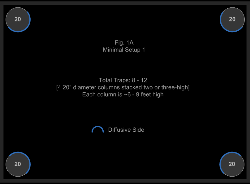
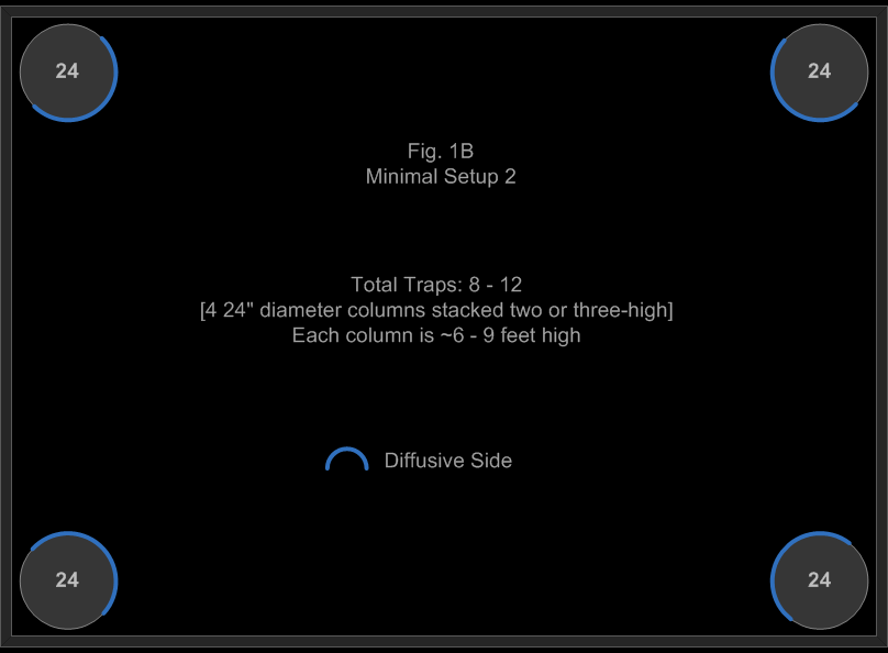
Because the corner Cylinder Traps will most likely be the furthest traps from the mic or listening position(s), we always recommend facing the diffusive sides of the corner traps toward the room, as shown in these illustrations.
Note: The standard height of a Cylinder Trap is 36". A "column" may consist of one or more Cylinder Traps stacked on one another.
ROOM SETUPS
MINIMAL ROOM SETUP 1 (FIG 1A)
This is our bare-bones minimal setup, and is a cost-effective starting point that can provide fair low-frequency control (8 20" Cylinder Traps). Note that better bass control will be achieved by stacking Cylinder Traps from floor to ceiling (12 20" Cylinder Traps).If reflections from remaining bare walls are an issue (not unlikely), foam-based products may be temporarily installed to tame these reflections until additional Cylinder Traps are added.
MINIMAL ROOM SETUP 2 (FIG 1B)
Similar to our bare-bones minimal setup above, this cost-effective starting point provides lower frequency control due to the larger diameter of the traps (8 24" Cylinder Traps). Note that better bass control will be achieved by stacking Cylinder Traps from floor to ceiling (12 24" Cylinder Traps).If reflections from remaining bare walls are an issue (not unlikely), foam-based products may be temporarily installed to tame these reflections until additional Cylinder Traps are added.
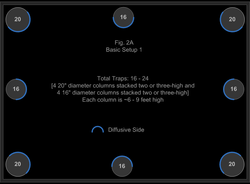
BASIC ROOM SETUP 1 (FIG 2A)
When adding broadband absorption at the half-way points in the room, mid-bass becomes tighter, and we begin to hear less slap-back echo with shorter, smoother reverb tails in this configuration.With this setup, the diffusive sides of all traps are facing into the room. For a drier, less lively, "tighter" sound, begin to move the diffusive sides of the 16" traps toward the wall to taste.
If reflections from remaining bare walls are an issue (not unlikely), foam-based products may be temporarily installed to tame these reflections until additional Cylinder Traps are added.
BASIC ROOM SETUP 2 (FIG 2B)
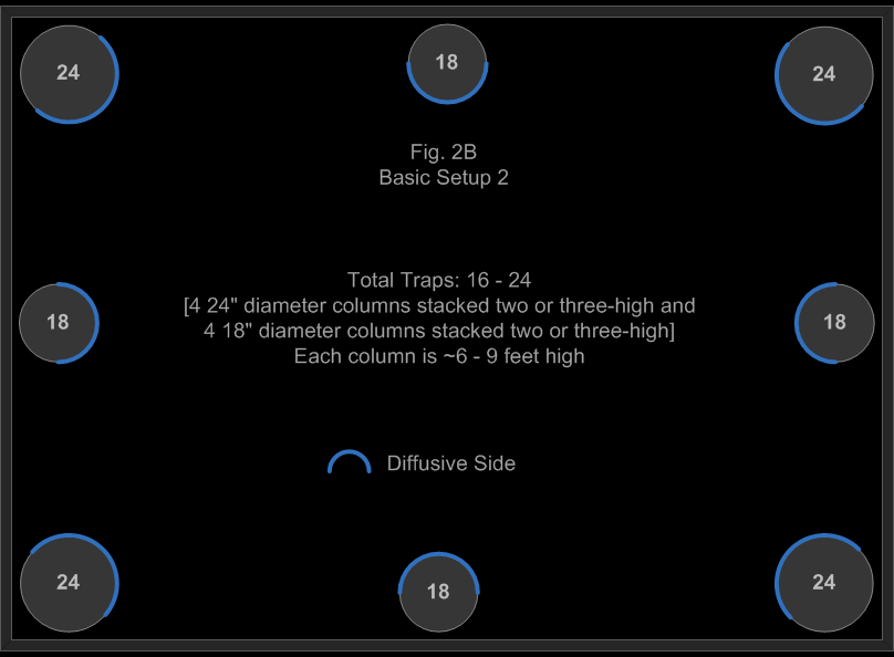
Similar to Basic Setup 1, however larger traps are utilized here to control lower frequencies.In this illustration, the diffusive sides of all traps are facing into the room. For a drier, less lively, "tighter" sound, begin to move the diffusive sides of the 18" traps toward the wall to taste.
If reflections from remaining bare walls are an issue (not unlikely), foam-based products may be temporarily installed to tame these reflections until additional Cylinder Traps are added.
INTERMEDIATE ROOM SETUP 1 (FIG 3A)
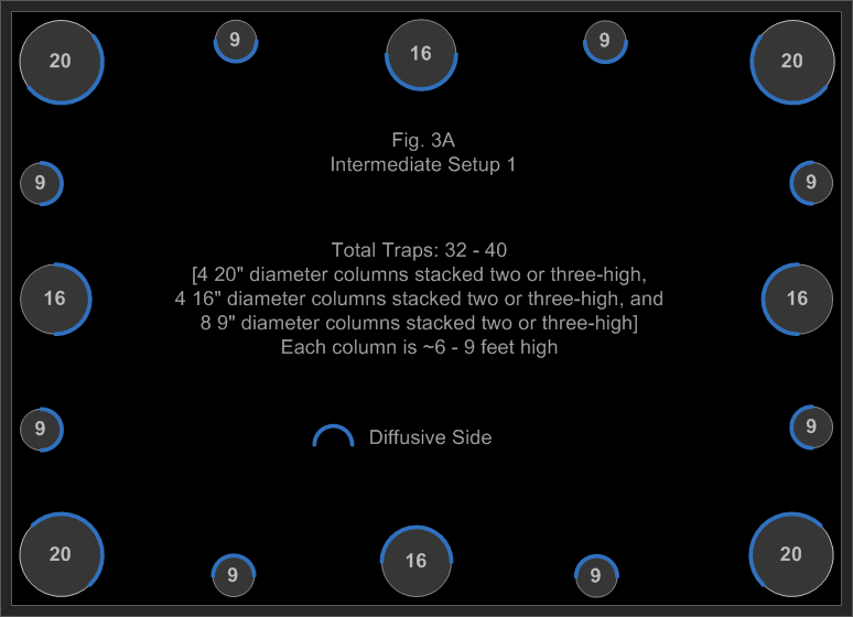
In this setup, we are getting close to the optimum treatment for the walls (we have not considered the ceiling yet). We have found that leaving 12 to 16" of wall space between the traps provides the most options in getting a good balance of absorption, reflection, and diffusion at typical recording and listening positions. As such, we recommend this distance range as a guideline.For the quarter points in the room (and smaller fractional points), we have found the 9" Cylinder Traps to be more than sufficient. However, we do not recommend the 9" size for carpeted floors. In that case, we recommend 11 or 13" Cylinder Traps. For better/lower frequency absorption, the first area to look at is the corner traps, then the half-points in the room. We recommend increasing the corner trap size first, then the half-point size second. For example, in this setup, we would increase the corner trap size from 20" to 24", and then the half-point trap size from 16" to 18".
In this illustration, the diffusive sides of all traps are facing into the room. For a drier, less lively, "tighter" sound, begin to move the diffusive sides of the 16" and 9" traps toward the wall to taste.
INTERMEDIATE ROOM SETUP 2 (FIG 3A)
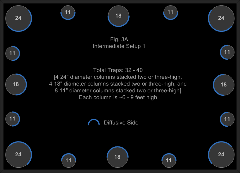
This setup is the same as Intermediate Setup 1, but we've replaced the 20" Cylinder Traps with the 24" models, and the 16" Cylinder Traps with the 18" models for better low frequency control. We've also replaced the 9" models with the 11" models.In this illustration, the diffusive sides of all traps are facing into the room. For a drier, less lively, "tighter" sound, begin to move the diffusive sides of the 18" and 11" traps toward the wall to taste.
ADVANCED ROOM SETUP (FIG 4A)
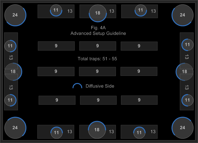
This setup is similar to Intermediate Setup 2 above, but includes ceiling treatment (10 13" Cylinder Traps in the ceiling corners, and 9 9" Cylinder Traps making up a ceiling cloud). 16" Cylinder Traps may be substituted for the 13" models for lower frequency bass control.In many smaller rooms and bedroom studios, the ceiling is typically closer to the mic and/or listening position(s), and depending on certain factors, may cause image smearing and other problems if neglected. If the lower frequencies are already well-controlled through corner trapping, a cluster of 9" Cylinder Traps for a ceiling cloud is usually sufficient and creates less bulk than larger models. The recommendation of 12 to 16" of ceiling space between traps still stands. However, depending on certain recording or listening scenarios, a closer distance may prove beneficial.
When mounting Cylinder Traps in ceiling corners as illustrated, columns of two stacked 36" high Cylinder Traps below them are typically sufficient. However, every room has unique requirements, which may vary depending on the goal.
In this illustration, the diffusive sides of all traps are facing into the room. For a drier, less lively, "tighter" sound, begin to move the diffusive sides of the wall traps toward the wall to taste. It is recommended that all ceiling corner traps, as well as standing corner traps, remain with the diffusive side of the trap facing into the room.
SPECIALTY SETUPS
RING OF CYLINDER TRAPS (FIG 5A)
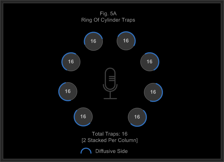
This is a cost effective "portable" recording space that can relatively decouple the outer room from its internal recording zone down to approximately 80 Hz. We recommend the 16" Cylinder Traps for this purpose because they are more stable, cover more area, and go deeper in frequency control compared to the smaller models.Unlike the reverberant room sound outside of the ring due to the room's bare walls, the sound inside the ring is noticeably drier and much more controlled, giving the engineer/artist many more options in post. The reverbant sound outside of the traps can still be captured with room mics, showing the power and flexibility of this setup. Rotating the traps on the fly will provide even more options, and can be achieved very quickly. Finally, expanding the ring can vary the "crosstalk" between the internal and external spaces.
When utilizing the diffusive sides of the traps in a ring unlike what is shown here (the diffusive sides of the traps are facing inward instead of outward), we strongly encourage critically listening to the results when the source and mic(s) are in close proximity to the traps (about five feet or less from the closest Cylinder Trap). Comb filtering may result if the diffusive sides of the traps are too close. The usual remedy is to move the traps further away from the source/mic(s). However, when doing so, the spacing between the traps become greater, requiring more of them to bring room decoupling to an acceptable level.
Another possible solution to the comb filtering problem is to mix up different sizes of Cylinder Traps in a ring to create more randomness in the diffusion. For good stability, the minimum recommended size for this setup is 13", the smaller traps being more susceptible to being knocked over.
MIX STATION (FIG 5B)
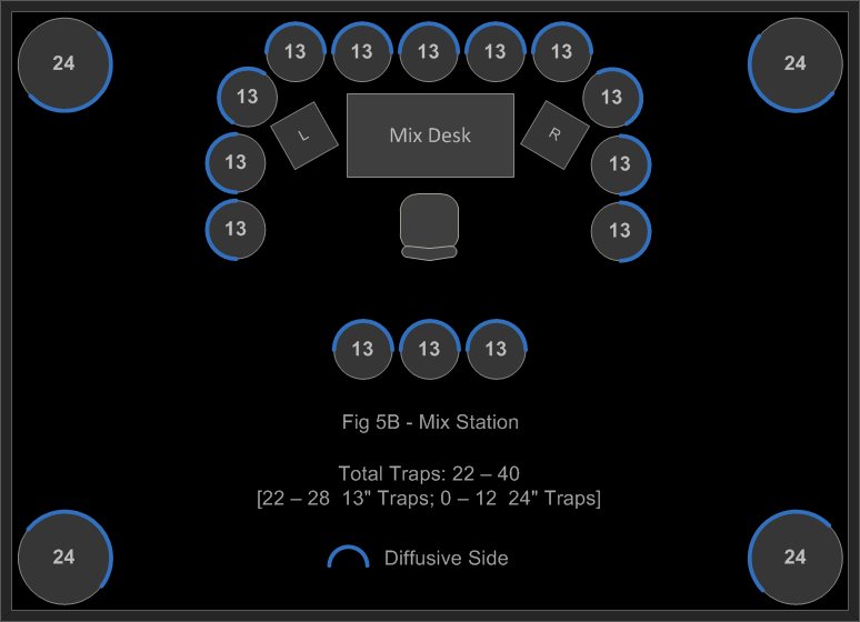
In this illustration, we are showing optional corner traps for deeper low frequency control, and rear diffusive traps to give a sense of more "space" behind the engineer/artist. The front and side 13" inch Cylinder Traps alone provide a very tight and precise audio image at the listening position, allowing a clearer picture of the mix. The rear traps provide back-scattered diffusion to help reduce the "black hole of sound" effect. Finally, the 24" corner traps provide a flatter response down in the very low and critical frequency ranges to improve accuracy and mix translation between varying systems.To obtain even greater focus, a ceiling cloud of 9" Cylinder Traps may be mounted above the engineer/artist and mixing desk.
